First a quick update: Yes I’m (kinda) still using this site to blog, obviously, my beloved adventure game engine hasn’t gotten much of the love it deserves in the past time, though. The reason for this is twofold: First, I finally made my PhD (yes, you may call me doctor now) the other one is, some time ago I started a new project: My very own pinball machine.
As I did not do my PhD in mechantronics or electronics, this is more of a learning excersise than a display of me doing the right thing from the start, so electronics pro’s please bear with the stupid mistakes you will find here ;-).
I’m starting out mostly with the electronics/software part and then will care for the mechanics, housing etc… (which is more or less an arbitrary choice though).
Basic Electronic Design Decisions
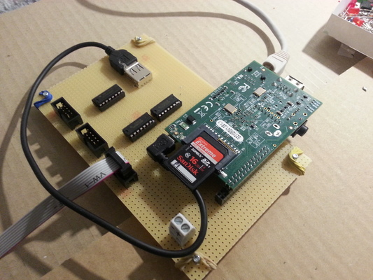
The “brain” of the machine will be a raspberry pi (as I happen to have one lying around, then there will be various boards devoted to different tasks such as:
- A display board using RG LED matrices for showing your score and other stuff
- A board that collects all kinds of switches (and possibly other kinds of input to the game)
- A driver board for the solenoid coils
- A driver board for lamps / LEDs
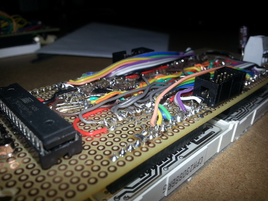
As I also happen to have an Arduino Uno board lying around, I use the Atmega328 as controller chip wherever I can, this makes programming and flashing a lot easier.
Communication
There are several options on how to implement communication between all these boards, like:
- Serial/UART communication
- I2C (which I dont know much about)
- Complex protocols (such as CAN, Ethernet, USB, you name it)
- SPI
UART communication is (or: can be) reasonably fast and is supported by the raspberry pi and virtually every microcontroller out of the box. However, it is designed for communication between exactly two partners which would require separate UART lines between the pi and all the controller boards or some trickery that would turn UART into a more bus-like thingy.
The more complex protocols are well… too complex as in not supported out of the box by the atmega and thus would require additional controllers and thus lead to more complexity.
I2C is probably not a bad choice at all, and in some regards seems similar to SPI on a first sight. However, because SPI was the first one I took a deeper look at, I went for SPI.
SPI is a simple communication protocol for a topology with exactly one master and multiple slaves, which matches the idea of having a raspberry pi as the brain plus a number of controller boards. SPI communication is controlled completely by the master which defines the communication timing and which slave is currently supposed to talk/listen. It defines the following lines:
- A clock line that defines when a valid bit can be read from the MISO/MOSI lines
- Master-in-slave-out (MISO): For communication from slave to master
- Master-out-slave-in (MOSI): For communication from master to slave
- A number of slave select lines, one for each slave, stating which slave is currently communicating with the master
As the number of slaves is hopefully limited, I’m hopeful that I will be able to fit all lines (including all the slave lines) in a 10-pin data cable I’ll use to connect all the boards.
There is much more to tell but for now I’ll stop here for dramatic effect. If you are very curious: What I have in terms of schematics and software is available at my pinball Github repository.
Stay tuned!