So I had this problem with my SPI communication: When using a “long” cable (not longer than 2m), SPI communication (between raspberry pi and switches board), would drop bits. And I’m not talking a bit flip here or there, I’m talking about a bit getting lost in the sense that all following bits where received in the wrong place and thus were useless. As you can imagine the amount of correctly received bytes was disastrous, even with 4kBit/s which seems to be the lowest SPI speed the raspberry can handle.
So here’s what I did:
- Making the AVR SPI slave as dumb (and thus fast) as possible. That didn’t help.
- Adding even more pauses/waiting times, after every single transmitted bit, didn’t help either.
- Bought a cheap hand-held oscilloscope (~175€), didn’t really show me anything wrong with the signal.
- Send back the cheap one and bought a “real” digital oscilloscope (although still in the low price segment with ~320€). The day the scope arrived was the day when I fixed the SPI transmission…
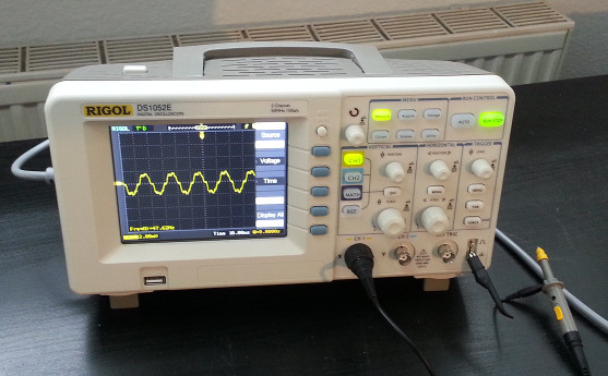
The scope is a RIGOL DS1052E. I’m not going to judge whether this is good or bad for the price, as I have basically nothing to compare it to and close to no experience with oscilloscopes so far. But what I can say its a very useful tool for SPI debugging (despite probably a million other things).
The first screen shot from my shiny new oscilloscope reveals the actual problem (here I showed the situation with 1MHz, as said above, the same happens with 4kHz already). The cyan line is the SPI clock given by the master, the yellow line is the slave select line that should stay at low for the whole transmission (when this goes high, the SPI slave will immediately stop transmission and ignore incoming data on the MOSI line).
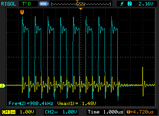
As you see, when clock levels change between high and low, the signal overshoots in the range of about 1V and then stabilizes. The overshoots by itself are not a real problem, all involved chips seem to handle it without any hassle. The problem occurs on the slave select line which mimics the overshooting behaviour. I’m still new to all this electronics stuff, but my guess is that this is either due to ground bounce or crosstalk on the cable.
Either way, the effect gets much worse, if MOSI and MISO also have vividly changing signals (not shown here), in that case I observed overshoots on the slave select line of up to ~2.5 volts. Now it becomes clear, why this is a problem: With such an overshoot, the slave considers the slave select line high and thus ignores bits until it is considered low again.
The solution
After some googling and reading about wave reflection in wires (of which I probably understood 10% ;)), I learned that there is a theoretical perfect way to kill the overshoots (which are actually waves of electrons being reflected in the wire), by adding a terminating resistor which must match the wave impedance of the wire. Thats probably the way to go if you want to sell your product or need really high speeds. However it depends on the type of wire, its exact length, so I decided it was not the way to go here.
But seemingly you can just insert a resistor into your wire line and it will “eat up” the incoming waves, effectively acting as a low-pass. You can see the effects here:
Without resistor:

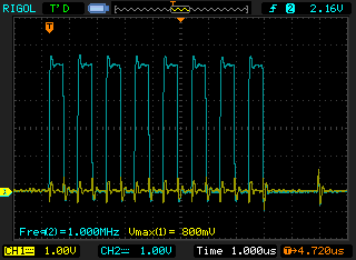
With 100 Ohm in MISO, MOSI, SCK and SS:
With 1 kOhm in MISO, MOSI, SCK and SS:
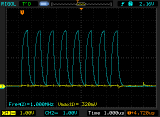
Although the last picture already looks horribly smooth for a digital signal, it actually seems to work well with 1MHz.
I will do some more reading up on this wave propagation and damping stuff, as I’m not really confident I know what I’m talking about here (as always, corrections/hints are welcome) and then maybe also try some different resistor values or termination techniques.